Industrial Worm Reducers Built for Australian Conditions
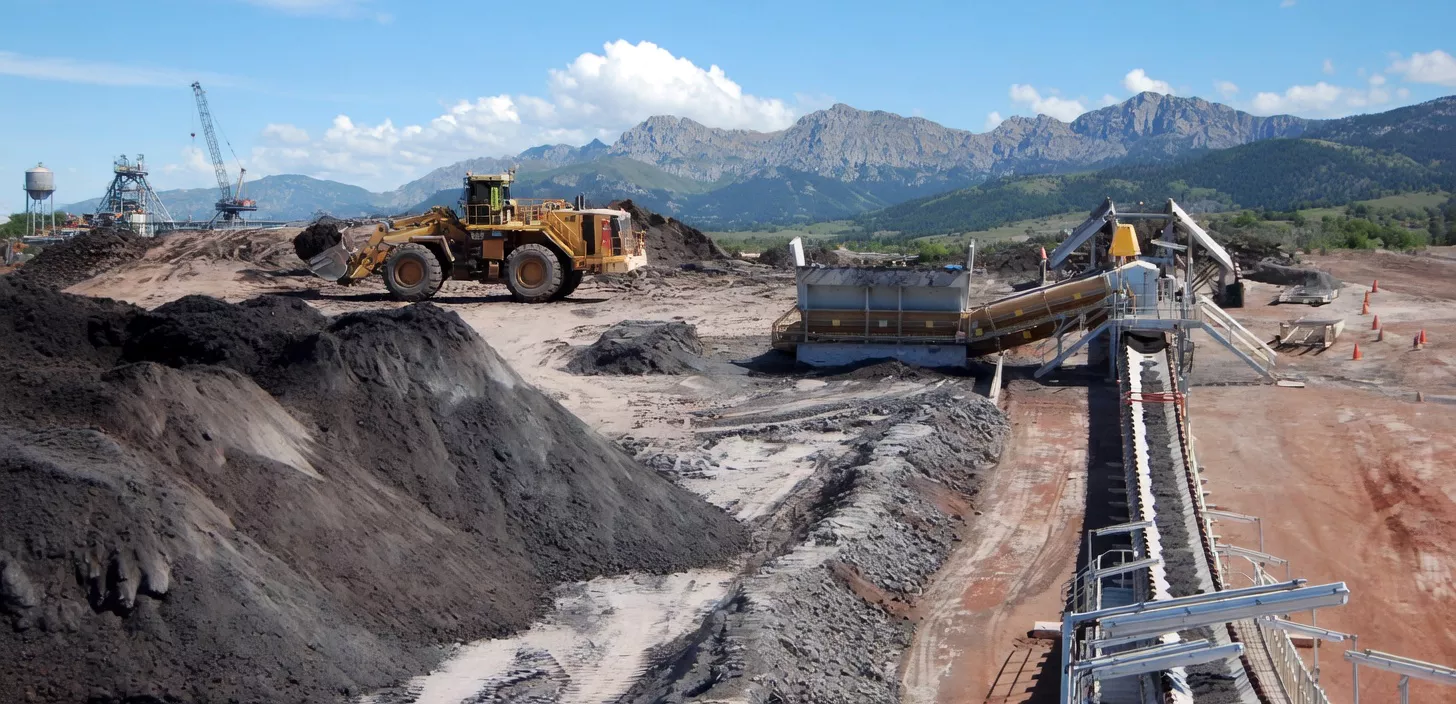
Reliable torque multiplication and speed reduction for mining conveyors, food-grade mixers, water treatment drives, and heavy materials-handling systems across Australia. Every gearbox is rated for continuous duty in ambient temperatures up to 50 degrees C and backed by an 18-month operational warranty.

Worm Gear Reducer Product Range
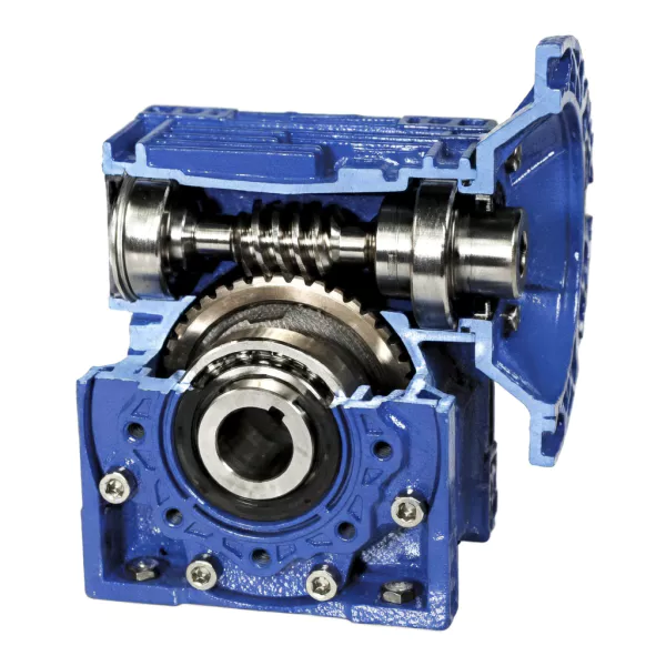
Every unit in our catalogue is designed around a single-enveloping or double-enveloping worm gear set, precision-hobbed from case-hardened alloy steel worms mating with centrifugally cast bronze wheels.

WPA / WPS Cast Iron Worm Reducer
FG260 cast iron housing for heavy-duty mining, water treatment, and manufacturing. Solid shaft input with five shaft-direction options (A/S/O/X/Z). Motor-flange (D) and hollow-shaft (K) variants available. Centre distances from 40 mm to 250 mm, output torque up to 2,745 Nm.
EPNMRV Aluminium Worm Gearbox
Die-cast ADC12 aluminium housing, 40% lighter than cast iron. IEC B5/B14 motor flanges, IP55 sealed, finned heat dissipation. Centre distances from 25 mm to 150 mm, output torque up to 16,508 Nm. The default choice for packaging, food processing, and overhead-mounted drives.

Double-Stage Worm Speed Reducer
Two worm gear sets in a single factory-aligned FG260 cast iron housing. Ratios from 100:1 to 3,600:1 for ultra-low-speed, high-torque applications including dam penstock actuators, large clarifier drives, and mining rotary equipment requiring output speeds below 5 RPM.

EPS Helical-Worm Combination Gearbox
A helical pre-stage increases overall efficiency from 60-85% to 80-92% by reducing the load on the worm mesh. This combination unit is the correct engineering choice when you need the compact right-angle output of a worm gear but cannot tolerate the thermal losses of a pure worm drive.

EPSS Stainless Steel Worm Reducer
304 stainless steel housing with IP69K washdown rating, VITON seals, and NSF H1 food-grade lubricant. Engineered for dairy, meat, beverage, and pharmaceutical environments where daily caustic cleaning destroys painted aluminium gearboxes. Both IEC and NEMA motor flanges.

Customised & High-Torque Worm Drives
For non-standard shaft configurations, extreme ratios, or output torques beyond our catalogue range, our engineering team develops bespoke worm reducer assemblies. Past projects include a 28,000 Nm slew drive for a solar tracker farm in South Australia and a triple-reduction unit for a dam penstock actuator in Tasmania.
Our product range extends beyond the series listed above. If you do not see the exact worm gearbox configuration you need, contact our engineering team — we can source, adapt, or custom-build a solution for your application.
Where Our Worm Reducers Work in Australia
We do not sell gearboxes into every sector. Below are the specific environments where a worm gear reducer is the technically correct drive solution, and where we have verified field performance.


What Sets an Ever-power Worm Reducer Apart
Our value is in the specifics. Below is exactly what separates an Ever-power worm reducer from commodity imports.
-
01
Multi-Material Worm Shafts Engineered for Your Application
We do not apply a one-material-fits-all approach. Standard-duty applications use 45# carbon steel worm shafts, quenched and tempered to HRC 45-50. High-load and continuous-duty drives use 20CrMnTi alloy steel, carburised to a case depth of 0.8-1.2 mm with surface hardness at HRC 58-62. For corrosive environments, we supply AISI 304 or 316L stainless worm shafts. Material selection is matched to your specific duty cycle, environment, and budget.
-
02
Centrifugally Cast Bronze Worm Wheels
Our worm wheels are centrifugally cast in ZCuSn10Pb1 (tin-bronze with 10% Sn, 1% Pb). Centrifugal casting eliminates the porosity and shrinkage defects common in gravity-cast or sand-cast bronze, producing a denser microstructure with measurably better fatigue resistance. The lead content provides a solid-lubricant reservoir at the tooth surface, reducing scoring risk during boundary lubrication conditions at start-up.
-
03
Full Thermal Rating per ISO 14179-1
Worm gears generate more heat than parallel-shaft gears because of the sliding contact. We rate every model's thermal power capacity using ISO 14179-1 calculation methods at a 40 degrees C ambient baseline, then de-rate for Australian conditions at 50 degrees C. Competitors frequently publish only mechanical ratings, leading to unexpected thermal failures in the field.
-
04
Engineer-Led Technical Support
Technical support is handled by degree-qualified mechanical engineers who can review your application, validate duty cycles, and issue formal selection reports with thermal calculations and efficiency curves. Every enquiry receives an engineering response within 24 hours. Reach our team at [email protected].
-
05
18-Month Operational Warranty
Every worm reducer ships with an 18-month warranty from date of commissioning (or 24 months from date of dispatch, whichever is earlier). Warranty coverage includes worm gear set replacement, housing defects, and seal failures. Claims are assessed by our engineering team within 48 hours, and replacement units are dispatched before the failed unit is returned.


Verified Quality, Documented Performance
Credibility is not a claim; it is a paper trail. Here are the standards and systems behind every unit we ship.
ISO 9001:2015 QMS
Manufacturing facility certified under ISO 9001:2015 with annual surveillance audits by TUV Rheinland. Quality management covers incoming material inspection (spectrometer verification of bronze and steel alloys), in-process dimensional checks (CMM measurement of worm lead, pitch, and profile), and final assembly torque testing.
CE Declaration of Conformity
All standard worm reducer models carry a CE Declaration of Conformity covering the Machinery Directive 2006/42/EC. While CE is an EU market requirement, many Australian OEMs and EPC contractors require it as evidence of baseline design safety analysis, particularly for equipment destined for export or multinational projects.
Material Test Certificates (MTCs)
We supply EN 10204 3.1 material test certificates for worm shaft steel and worm wheel bronze on request. MTCs are issued by the raw material mill, not self-certified, and include chemical composition, mechanical properties, and heat treatment records. Essential for mining and infrastructure projects with full traceability requirements.
OEM & Private-Label Supply
We manufacture worm gearboxes under private label for four Australian OEM equipment builders in the food machinery and conveyor sectors. OEM agreements include locked revision control on drawings, dedicated production slots, and pre-shipment inspection reports with photographs. Speak with our engineering team to discuss OEM arrangements.
Noise & Vibration Testing
Every unit is run-in at the factory for a minimum of 30 minutes under load before dispatch. Output vibration is measured per ISO 8579-2 and must fall below 2.8 mm/s RMS velocity at any bearing location. Units that exceed the threshold are re-shimmed or rejected. Test reports are available on request.
Lubricant & Seal Specifications
Standard fill is a fully synthetic PAO 220 gear oil rated for continuous operation at 180 degrees C. Seals are NBR as standard, with Viton (FKM) available for high-temperature or chemically aggressive environments. Seal lip contact pressure and shaft surface finish are controlled to DIN 3760 to ensure a minimum seal life of 10,000 hours.
What Our Clients Say
Feedback from engineers, procurement managers, and maintenance supervisors who have installed Ever-power worm reducers in live production environments across Australia.
"We replaced 24 competitor-brand worm reducers on our feeder conveyor line with Ever-power WPA 250 units. After 14 months of continuous operation in 47 degrees C ambient, zero unplanned stoppages and no measurable worm wheel wear beyond normal running-in. The thermal de-rating for our Pilbara conditions was the detail that made the difference — previous supplier never mentioned it."
"The SS316L NMRV gearboxes on our vat mixer drives have survived daily caustic washdown for over 8 months now with zero lubricant leakage. Getting the Viton seal upgrade and FDA H1 oil as standard was critical for our HACCP audit. Ever-power's engineer even provided a C-face adapter drawing to match our existing Bonfiglioli motor mounts — saved us from re-machining the frames."
"We needed a 900:1 ratio at 0.8 RPM output for a 30-metre clarifier scraper drive. Ever-power engineered a custom double-stage unit with Hempel epoxy coating for our H2S environment. It has been running continuously for 16 months without a single service call. The selection report they provided — with full thermal calculations at our site ambient — gave us the confidence to approve the purchase order."
The Complete Buyer's Guide to Worm Reducers for Australian Applications
This section helps engineers, maintenance supervisors, and procurement managers make technically sound decisions when specifying a worm gear reducer. Click each topic to expand.
How a Worm Gear Reducer Works
▾A worm reducer is a right-angle gear drive consisting of two elements: a cylindrical worm (the input) and a toothed worm wheel (the output). The worm is essentially a screw, typically with one to four thread starts, that meshes with the helical teeth cut into the periphery of the worm wheel. As the worm rotates, its threads push against the worm wheel teeth, causing the wheel to turn at a reduced speed and increased torque.
The gear ratio is determined by dividing the number of teeth on the worm wheel by the number of thread starts on the worm. A 40-tooth worm wheel driven by a single-start worm produces a 40:1 ratio. A double-start worm with the same wheel gives 20:1. This is why worm reducers can achieve very high ratios (up to 100:1 single-stage) in a compact package that no spur or helical gear set can match at the same centre distance.
The contact between a worm and wheel is fundamentally a sliding contact, unlike the rolling contact that dominates spur and helical gear meshes. This sliding action is both the advantage and the limitation of worm gearing: it creates a smooth, quiet, shock-absorbing power transmission, but it also generates more frictional heat and results in lower efficiency compared to parallel-shaft gear trains.
When to Use a Worm Reducer (and When Not To)
▾A worm gear reducer is the correct technical choice when your application demands one or more of the following:
- A compact right-angle drive with a high single-stage ratio (10:1 to 100:1).
- Self-locking or backstop capability to prevent the load from back-driving the motor (typically achieved at ratios above 40:1 with a single-start worm).
- Low noise and smooth operation, important in indoor and food-processing environments.
- Shock-load absorption, as the sliding mesh acts as a natural damper.
A worm reducer is not the best choice when:
- Efficiency above 90% is critical and the drive runs continuously at high load (consider a helical-bevel reducer instead).
- High-speed output is required (worm gears are designed for speed reduction, not speed increase).
- Bidirectional backstop is needed (worm gears only resist back-driving in one direction).
Key Parameters for Selecting a Worm Gearbox
▾1. Output Torque
Define the torque required at the output shaft under the worst-case operating condition, including any service factor for shock loading. AGMA 6034-B92 provides service factor tables for different load classes: uniform (SF = 1.0), moderate shock (SF = 1.25-1.5), and heavy shock (SF = 1.75-2.0). Undersizing the torque requirement is the most common cause of premature worm wheel wear in the field.
2. Gear Ratio
Calculated as motor speed divided by required output speed. If the required ratio exceeds 60:1 in a single stage, consider either a double-stage worm reducer or a helical-worm combination to avoid excessive efficiency loss.
3. Thermal Power Rating
The maximum continuous power the gearbox can transmit without exceeding its allowable oil sump temperature (typically 90-100 degrees C). In Australia's climate, always verify that the thermal rating is sufficient at your site's peak ambient temperature, not just the catalogue's default 20 degrees C baseline.
4. Mounting Position
Worm reducers are sensitive to mounting orientation because it affects lubrication of the worm gear mesh. Most standard units are designed for horizontal worm shaft (B3/B8 mounting per IEC). Vertical worm shaft configurations often require modified oil level plugs and additional sealing.
5. Input and Output Shaft Configuration
Specify whether you need a solid input shaft, hollow input shaft (for direct motor slide-on), solid output shaft, hollow output shaft (for shaft-mounted installation), or a flanged output for direct coupling. Mismatched shaft specifications are the second most common ordering error after torque undersizing.
Worm Reducer Efficiency: What the Datasheets Do Not Tell You
▾Published efficiency figures for worm reducers are measured under ideal laboratory conditions. Real-world efficiency is affected by several factors rarely discussed in sales literature:
- Running-in period: New worm gears operate at 5-10% lower efficiency for the first 100-200 hours until the contact surfaces conform.
- Partial load: Efficiency drops significantly at partial loads because the fixed frictional losses become a larger proportion of the transmitted power.
- Temperature: Lubricant viscosity decreases at high temperature, thinning the oil film and increasing metal-to-metal contact.
- Worm lead angle: Higher lead angles (more thread starts) yield higher efficiency.
| Ratio | Thread Starts | Approx. Efficiency | Self-Locking? |
|---|---|---|---|
| 5:1 | 4 | 90-93% | No |
| 10:1 | 4 | 87-90% | No |
| 20:1 | 2 | 78-85% | Marginal |
| 40:1 | 1 | 65-75% | Yes |
| 60:1 | 1 | 55-65% | Yes |
| 100:1 | 1 | 45-55% | Yes |
Lubrication Best Practices for Australian Conditions
▾Lubricant selection and maintenance are the single biggest controllable factor affecting worm reducer service life. For standard industrial environments in Australia, we recommend a fully synthetic polyalphaolefin (PAO) gear oil, ISO VG 220 or VG 320, with an EP additive package designed for bronze-on-steel contact. Do not use conventional sulphur-phosphorus EP additives intended for steel-on-steel gears, as these will chemically attack the bronze worm wheel surface.
Oil change intervals depend on operating temperature: at a continuous sump temperature below 80 degrees C, change oil every 10,000 hours or 24 months, whichever comes first. Above 80 degrees C, halve the interval. In dusty environments such as quarries and mines, consider fitting a desiccant breather and sampling the oil for particulate count at 3-month intervals.
Common Failure Modes and How to Prevent Them
▾Worm Wheel Tooth Wear
The most common failure mode. Wear accelerates when the lubricant film breaks down due to overloading, high temperature, or contamination. Prevention: size correctly with an appropriate service factor, maintain lubricant quality, and monitor oil temperature.
Pitting on the Worm Wheel
Sub-surface fatigue cracking caused by repeated Hertzian contact stresses. If pitting appears prematurely (under 5,000 hours), it usually indicates an alignment problem or an overload condition. Prevention: ensure coaxiality within manufacturer tolerance (typically 0.05 mm TIR).
Thermal Seizure
Occurs when the gearbox exceeds its thermal rating, lubricant viscosity collapses, and the worm and wheel seize together. Prevention: always check the thermal power rating at your site's actual ambient temperature. In enclosed spaces, specify a shaft-mounted cooling fan or oil-to-air heat exchanger.
Seal Failure and Lubricant Leakage
Output shaft seals degrade due to heat ageing, chemical attack, or shaft surface damage. Prevention: specify Viton (FKM) seals for temperatures above 100 degrees C. Ensure shaft surface finish under the seal lip is Ra 0.4 or better, and replace seals proactively at every second oil change.
Worm Gear Standards and Specifications Referenced
▾When specifying a worm reducer for an Australian project, the following standards are commonly referenced:
- AGMA 6034-B92 — Practice for Enclosed Cylindrical Wormgear Speed Reducers and Gearmotors
- AGMA 6022-C93 — Design Manual for Cylindrical Wormgearing
- DIN 3975 — Terms and Definitions for Cylindrical Worm Gears
- ISO 14179-1 — Thermal Power Rating of Gearboxes
- ISO 8579-2 — Noise and Vibration Code for Gearboxes
- AS 1403 — Design of Rotating Steel Shafts
For project-specific engineering support, including selection validation, thermal calculations, and CAD models, contact our technical team or email [email protected].
Get Expert Worm Reducer Sizing Support
Submit your application parameters — torque, ratio, mounting, environment — and our engineers will return a formal selection report within 24 hours, including thermal rating verification and 2D/3D drawings.
Continue Your Research
Whether you need to understand our manufacturing capability, review a specific product series, or speak with an engineer, these pages will help.